 English
 Español
 Português
 русский
 Français
 日本語
日本語 Deutsch
 tiếng Việt
 Italiano
 Nederlands
 ภาษาไทย
 Polski
 한국어
한국어 Svenska
 magyar
 Malay
Malay বাংলা ভাষার
 Dansk
Dansk Suomi
Suomi हिन्दी
 in Handheld Devices - News - SZ Hongjia Technology Shares Limited")

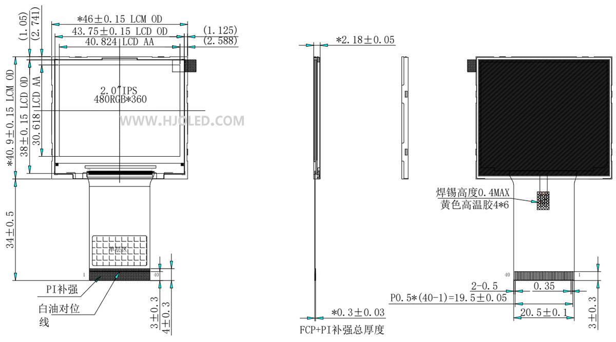
Hardware Design Techniques for 2.0-inch HD TFT Displays (480*360 Resolution, RGB Interface) in Handheld Devices
Hardware design for a 2.0-inch HD landscape display (480*360 resolution, RGB interface) in handheld devices centers on balancing display quality, power consumption, physical space, and reliability. The following are key design techniques and considerations summarized by engineers at Shenzhen Hongjia Technology:
I. Interface and Signal Integrity
1. RGB Interface Selection
Prioritize the use of RGB565 (16-bit) or RGB666 (18-bit) parallel interfaces to ensure sufficient data bandwidth for 480*360 resolution at 60Hz (requiring a pixel clock of approximately ~20MHz).
If the interface voltage of the main controller does not match that of the LCD (e.g., 1.8V vs. 3.3V), a level-shifting IC (such as the TXS0108E) or a resistor divider combined with a buffer must be added.
2. Signal Routing Optimization
Length Matching and Impedance: It is recommended that RGB data lines (D[0:17]) be length-matched within their group (with a deviation of ≤100 mils); the clock line (PCLK) should be length-matched independently and routed away from high-speed noise sources.
Ground Guarding and Shielding: On the FPC (Flexible Printed Circuit) or PCB, use GND lines to isolate RGB signals from noise sources such as the backlight PWM and power supply lines.
Termination Matching: If the transmission distance exceeds 10cm, a series resistor (22Ω–100Ω) may be added at the LCD end to suppress signal reflections.
II. Power Supply and Power Consumption Control
1. Multi-Channel Power Supply Design
Typical requirements include: VDD (logic voltage, typically 3.3V/1.8V), VCI (driver voltage, ~3.3V), and backlight LED drive voltage (ranging from 3.5V to 20V, depending on the number of LEDs in series).
It is recommended to use a low-noise LDO (such as the TPS7A47) to supply VDD and VCI, thereby preventing ripple noise from switching power supplies from interfering with display uniformity.
2. Backlight Power-Saving Strategies
This specific display features a backlight comprising 6 LEDs, delivering a high brightness of 800 nits to ensure clear readability even under direct sunlight. Alternatively, a high-efficiency LED driver IC (such as the LP8556) can be employed to support a hybrid control scheme combining PWM dimming (recommended >1 kHz to prevent flickering) and analog dimming.
Automatic Brightness Adjustment: Incorporate an ambient light sensor (such as the APDS-9301) to dynamically adjust the backlight based on ambient lighting conditions, thereby achieving power savings of over 30%.
3. 2.0-inch HD TFT Display: This is a landscape-oriented display featuring a high-definition resolution of 480 × 360 pixels. It utilizes the ST7701S driver IC and an RGB interface. When designing the mainboard, it is essential to verify that the host CPU supports high-resolution displays and the RGB interface to prevent scenarios where the CPU lacks the capacity to drive the display effectively. The 480 × 360 landscape configuration has a 4:3 aspect ratio; therefore, the scan direction must be correctly configured during software initialization (typically via the MV/MX/MY bits of the 0x36 command) to prevent the displayed image from being rotated by 90 degrees.
III. EMC and Interference Immunity
1. LCD Module Shielding
Place conductive foam between the backlight module and the PCB; additionally, wrap the FPC (Flexible Printed Circuit) in copper foil and ground it to minimize radiated noise.
2. Power Supply Decoupling
At each power supply input, install a 10 μF ceramic capacitor in parallel with a 0.1 μF high-frequency capacitor, positioning them in close proximity to the LCD connector.
3. Synchronization Signal Protection
Insert ferrite beads (such as the BLM18PG121SN1) in series with the HSYNC and VSYNC signals to filter out high-frequency noise.
IV. Testing and Verification
1. Power-Up Sequence VerificationConfirm that the power supply and signal timing sequences for both the host controller and the LCD module comply with the requirements specified in their respective datasheets (e.g., a reset pulse width of >10 ms).
2. Display Quality Testing
Utilize solid-color and checkerboard test patterns to inspect for color blotches, flickering, and image persistence (ghosting). Use an oscilloscope to measure PCLK (pixel clock) jitter; this value should remain below 5% of the clock period.
3. ESD Protection
Install a TVS diode array (such as the SRV05-4) at the FPC interface to ensure compliance with the IEC 61000-4-2 Level 4 standard.
Through the implementation of the aforementioned design strategies, it is possible to achieve stable, high-definition display performance within a limited physical footprint, thereby extending the battery life of handheld devices. We recommend that, once a prototype is produced, priority be given to testing power consumption and EMI, as well as conducting FPC durability validation in preparation for mass production. Shenzhen Hongjia Technology boasts 12 years of specialized expertise in the R&D, manufacturing, and sales of display screens ranging from 1.14 to 12.1 inches, along with their accompanying touchscreens. Our comprehensive product range includes high-definition, high-brightness, and irregularly shaped displays, featuring a wide variety of interface options. Operating from our own dedicated manufacturing facilities equipped with fully automated production machinery, we proudly serve numerous Fortune 500 companies worldwide. Furthermore, we offer a 36-month after-sales service guarantee, ensuring you enjoy complete peace of mind.
Send Inquiry


X
We use cookies to offer you a better browsing experience, analyze site traffic and personalize content. By using this site, you agree to our use of cookies.
Privacy Policy