 English
 Español
 Português
 русский
 Français
 日本語
日本語 Deutsch
 tiếng Việt
 Italiano
 Nederlands
 ภาษาไทย
 Polski
 한국어
한국어 Svenska
 magyar
 Malay
Malay বাংলা ভাষার
 Dansk
Dansk Suomi
Suomi हिन्दी

Small and Medium Size LCD Screen-Optical Design of Backlight Display
Backlighting is used in small, light, flat-panel liquid crystal displays (LCDs) and other electronic devices that require backlighting, including handheld devices as small as the palm of your hand, and large-screen TVs. The goals of backlight design include low power consumption, ultra-thin, high brightness, uniform brightness, large area, and control of different width and narrow viewing angles. To achieve these challenging design goals with controlled cost and rapid implementation, computer-aided optical design tools must be used for design. This article introduces the characteristics of LightTools optical design and analysis software from ORA Company in the United States, which can be used to develop the most advanced backlight design applications today.
Optical Design and Analysis Tools for Backlighting
A backlighting system requires some conversion of light from one or more light sources to produce the required light distribution in an area or at a fixed angle. Lighting design software must be able to model geometrically, set optical characteristic parameters for different types of light sources and conversion units, and must be able to use optical tracing methods to evaluate the path of light through the model and calculate the final light distribution. Light distribution uses Monte Carlo simulations to calculate illuminance, luminance, or luminous intensity for specific areas and/or angles. Light rays are emitted from the light source at random positions and angles, traced through the optical system, and received on the receiving surface. Illuminance can be calculated from surface receivers and intensity can be obtained from far-field receivers. By defining a luminance meter on the receiver surface, the spatial and angular distribution of luminance can be calculated. In some cases, it may be important to analyze the chromaticity of a display. Specify the spectral energy distribution of light sources (such as light-emitting diodes), output CIE coordinates and correlated color temperature (CCT), quantify the chromaticity of the display, and generate RGB real light rendering graphics on the display. These analyzes can all be done in LightTools software.
The characteristics of backlit displays place special demands on lighting analysis software. As will be explained, the light emitted by the backlight depends on the distribution density of printed dots, or the distribution pattern of microstructures. For the modeling of specific microstructure arrays, if the CAD model is used directly, the model size may be very large. LightTools software provides functions defined by 3D texture arrays, which can perform accurate ray tracing and rendering. Since no directly constructed geometric model is used, the size of the model is smaller and ray tracing is faster. Another aspect of backlight analysis includes the splitting and scattering of light on the surface of the light guide plate. Since lighting effects are simulated using Monte Carlo methods, it is possible that extensive ray tracing must be used to obtain a design with sufficient accuracy. The most efficient way is to trace the highest energy ray. By tracing the highest energy ray path using split probabilities and using the target area or scattering angle of the scattering surface to direct the scattered light to "important" directions (such as towards the viewer of the display).
Shenzhen Hongjia Technology specializes in R&D and production of LCD screens with various brightness. The brightness of the backlight is uniform. The overall brightness of the module can reach 2000 lumens. It is clearly readable in sunlight. The working temperature can reach -35 to 85 degrees. Antistatic with iron frame Well, drop performance is superior.
What is backlight?
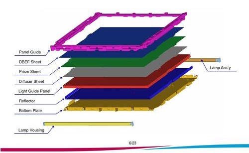
A typical backlight consists of a light source, such as a cold cathode fluorescent lamp (CCFL) or light emitting diode (LED), and a rectangular light guide. Other available components include diffuser plates, which improve the uniformity of the display, and brightness enhancing films (BEF), which increase the brightness of the display. The light source is usually located at one side edge of the light guide plate to reduce the thickness of the display. Edge lighting typically uses total reflection (TIR) to direct light in the display.
Backlight designers have several ways to model light sources in LightTools software. Different shapes of fluorescent light sources (such as straight, L-shaped, U-shaped or W-shaped, as shown in Figure 2) can be quickly defined using the fluorescent lamp creation tool. The lamp reflector can be defined with various geometric primitives in LightTools software, such as cylinders, elliptical slots, and extruded polygons. Reflectors defined in CAD systems can also be imported into LightTools software via standard data exchange formats (IGES, STEP, SAT and CATIA). If LEDs are used, designers can select desired LED models from the pre-stored product models of Agilent, Lumileds, Nichia, Osram, etc. in the LightTools software. Once the light enters one side of the LGP, the problem becomes to extract the light from the LGP perpendicular to the direction of propagation.
As shown in FIG. 3 , the brightest side of the light guide plate is near the light source, and the brightness in the light guide plate becomes darker as the distance increases. For uniform light output, light extraction efficiency must increase with distance. One of the main tasks in backlight design is to design a light guide plate that varies the light extraction efficiency as desired. There are two extraction techniques that can be used. The dot printing light extraction technology is to print a dot matrix structure on the bottom of the light guide plate to scatter the light upwards and emit it from the surface of the light guide plate. The second technology, Molded Light Extraction Technology, relies on total reflection (TIR) of the bottom surface microstructure to cause light to emerge from the surface of the LGP.
LightTools software provides backlight design tools to realize the design of the light guide plate. This tool (Figure 4) assists the user in creating the various components of the backlight. Other options include adding a light source/reflector component to the model, BEF modeling, and building a receiver to analyze brightness. The backlight tool's interface is a collection of tabs for setting up and modifying various types of light extraction mechanisms.
For the backlight using the dot printing light extraction method, the backlight tool can set the linear change of the size and aspect ratio of the printed dots, and the linear change of the dot spacing along the length of the light guide plate. This linearly varying structure is often a good starting point for displaying uniformity, but it is not sufficient for final uniformity requirements. Further control over uniformity can be achieved using non-linearly varying ray extraction parameters. A method with the fewest number of parameters and very flexible control is to define parametric variables of the quadratic Bézier curve. The 2D region tool of LightTools software can be used to set up non-linear structures. Figure 5 shows an example of using printed extraction, where 3 parameters (printed dot width, height and vertical spacing) are varied to obtain different extraction behaviors. The output uniformity is shown in Figure 6. The figure on the right shows that the average output brightness is a constant.
Send Inquiry


X
We use cookies to offer you a better browsing experience, analyze site traffic and personalize content. By using this site, you agree to our use of cookies.
Privacy Policy