English
 Español
 Português
 русский
 Français
 日本語
 Deutsch
 tiếng Việt
 Italiano
 Nederlands
 ภาษาไทย
 Polski
 한국어
 Svenska
 magyar
 Malay
 বাংলা ভাষার
 Dansk
 Suomi
 हिन्दी

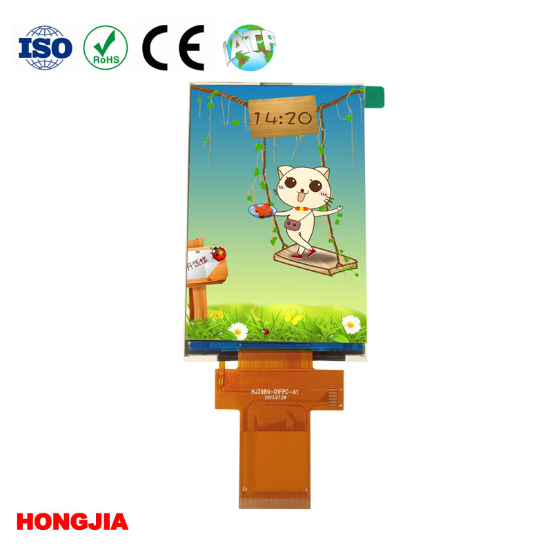
A 3.98-inch panel will often be grouped with 4.0-inch displays in catalogs, distributor filters, and engineering discussions. That rounding is convenient for product classification. It is not a statement that two modules share the same outline, connector, pinout, software, or optical performance.
This is where buyers get caught. The diagonal difference looks negligible, so a replacement is approved before anyone checks the FPC drawing or active area. The module arrives, and the mounting window clips the image, the tail exits in the wrong direction, or the existing controller cannot drive the selected interface.
The short answer: diagonal labels describe a size class, not guaranteed interchangeability
No. A 3.98-inch TFT LCD and a display sold as 4.0 inches may be functionally similar, but the labels alone do not establish interchangeability.
The diagonal normally describes the panel’s image size, often with rounding conventions that vary among suppliers. It says little about the complete module. Two products in the same nominal size class can have different glass outlines, active areas, viewing windows, resolutions, aspect ratios, FPC locations, interface configurations, backlight requirements, touch assemblies, and controller commands.
HONGJIA’s 3.98-inch IPS TFT LCD module, for example, is identified as a 320 × 480 IPS module using an ILI9488 driver IC, with SPI, MCU, and RGB interface options. Those details provide a starting point for comparison. They do not make every 4.0-inch TFT LCD a substitute.
Use a four-layer comparison to determine whether two display modules can substitute for each other
Evaluate substitution through four layers: mechanical fit, optical fit, electrical fit, and control compatibility. A module has to pass all four. Matching three out of four still leaves you with a redesign, not a drop-in replacement.
Mechanical and optical fit: outline, active area, viewing area, orientation, FPC position, bezel, and touch stack
Start with the controlled drawings rather than the catalog title. Compare the module outline, glass dimensions, thickness, active area, recommended viewing area, corner geometry, datum locations, and tolerances. Check whether the display is portrait or landscape in its native orientation and where pixel row one begins. A correct diagonal does not guarantee that the visible image will line up with an existing enclosure window.
The FPC deserves its own review. Its exit edge, bend direction, stiffener, length, contact pitch, contact side, and connector insertion direction can determine whether the module fits the assembly. A tail that is only slightly different may collide with a PCB, battery, gasket, or housing rib.
Optically, compare IPS viewing behavior, transmissive construction, color information, backlight brightness options, and the complete stack above the LCD. A selectable brighter backlight does not, by itself, establish that a module is sunlight readable. Outdoor performance also depends on reflections, cover-lens treatment, bonding, contrast under ambient light, and thermal conditions.
If touch is required, include the sensor, adhesive or optical bonding layer, cover lens, touch FPC, and controller in the dimensional review. A 3.98-inch TFT LCD with touch-screen options may have a very different overall thickness and bezel requirement from the bare LCD module.
Electrical and control fit: pinout, voltage requirements, interface, driver IC, backlight circuit, and initialization
Do not treat connector compatibility as electrical compatibility. Two FPCs can have the same pin count while assigning power, ground, data, synchronization, reset, and backlight functions to different contacts. Compare the pin table line by line, including logic levels, supply rails, power sequencing, reset timing, and any unused pins that must be tied to a defined state.
The backlight is another common failure point. Confirm the LED arrangement, required drive conditions, dimming method, connector routing, and whether the host board or module provides the necessary current control. Never connect a replacement backlight based only on wire count.
Control compatibility includes the interface mode, driver IC, initialization sequence, pixel format, scan direction, timing parameters, and sleep or wake behavior. Even where both modules use an ILI9488, firmware should not be assumed identical. Panel-specific settings can affect orientation, color order, inversion, porch timing, and image stability.
Choose among HONGJIA’s listed SPI, MCU, and RGB options according to the host architecture
The best interface is the one your processor and image-update requirements can support without awkward conversion hardware.
- SPI reduces signal count and can simplify routing in compact products. Its serial transfer rate may be the limiting factor when you need frequent full-screen updates or animation.
- MCU interface suits hosts designed around a parallel display bus. It uses more pins than SPI but can move display data more directly, subject to the selected bus configuration and controller timing.
- RGB interface is appropriate where the host supplies a continuous pixel stream and the required synchronization signals. It places different demands on the processor, memory architecture, timing setup, and PCB routing.
Interface names are categories, not complete interface specifications. Before selecting the listed SPI, MCU, or RGB 3.98-inch display configuration, obtain the exact pinout and timing documentation for that configuration. Do not assume all three options use the same FPC or can be changed through firmware alone.
A 320 × 480 IPS panel with an ILI9488 still requires configuration-specific sample bring-up
Resolution, panel technology, and driver IC narrow the field, but they do not finish the qualification. A 4.0-inch TFT LCD with 320 × 480 pixels may present the same nominal image format as HONGJIA’s published 3.98-inch module while differing everywhere that affects integration.
Bring up samples on the intended host board. Verify power-on and reset behavior, initialization, full-screen color patterns, color order, scan direction, edge pixels, sleep recovery, backlight dimming, and operation across the required temperature range. Run the display long enough to expose intermittent FPC contact, timing instability, image flicker, or thermal behavior that a brief bench test can miss.
This sample stage also shows whether the chosen interface has enough practical update speed. A static instrument screen and a touch-driven user interface place very different loads on the same 320 × 480 display.
Customization creates a new qualification baseline rather than an automatic drop-in variant
Customization can solve a real packaging or supply problem, but every requested change creates a configuration that must be documented and approved. Treat it as a new baseline, even if the LCD glass and driver IC remain unchanged.
Separate published specifications from requested changes to the FPC, touch screen, backlight, cover lens, or interface
Mark the supplier’s published module specifications separately from requested modifications. A custom FPC can change the outline, contact arrangement, bend behavior, or assembly process. Adding capacitive touch introduces another controller, communication link, tail, optical stack, and firmware task. A different backlight may alter brightness, power demand, heat, or mechanical thickness.
Cover-lens dimensions, printing, surface treatment, and bonding method also affect enclosure fit and outdoor readability. Record these as explicit requirements rather than assuming they are included under the broad term “custom display.”
Control approved drawings, samples, revisions, applicable compliance records, and long-term production continuity
The purchasing part number should point to an approved drawing and revision, not merely to “3.98 inch TFT LCD IPS” or “4-inch display.” Keep a signed sample or other agreed reference where appearance matters. If your application requires compliance documentation, request the records applicable to the exact module and materials; do not infer them from another product in the same family.
Long-term supply also depends on revision control. Define how changes to the panel, driver IC, FPC, backlight LEDs, touch controller, adhesive, or production site will be communicated and requalified. Small-quantity availability and FAE support are useful during development, but they do not replace an agreed production configuration.
Go/no-go checklist before treating a 3.98-inch module as a 4.0-inch replacement
- Do the outline, thickness, active area, viewing area, orientation, tolerances, and mounting datums fit the existing enclosure?
- Does the FPC exit in the correct location, and do its pitch, contact side, stiffener, length, and pin assignments match?
- Are the supply rails, logic levels, power sequence, reset timing, and backlight drive requirements compatible?
- Does the selected SPI, MCU, or RGB configuration match the host hardware and required screen-update rate?
- Have you verified the exact driver initialization, pixel format, color order, scan direction, sleep recovery, and timing?
- Does the optical stack meet the required viewing, brightness, ambient-light, and temperature conditions?
- If touch is fitted, have you qualified the sensor, controller, cover lens, bonding method, touch FPC, and total thickness?
- Are the approved drawing, sample, revision, applicable compliance records, and change-notification terms tied to the purchasing part number?