 English
 Español
 Português
 русский
 Français
 日本語
日本語 Deutsch
 tiếng Việt
 Italiano
 Nederlands
 ภาษาไทย
 Polski
 한국어
한국어 Svenska
 magyar
 Malay
Malay বাংলা ভাষার
 Dansk
Dansk Suomi
Suomi हिन्दी
What Are the Interface Requirements for a 3.1-Inch 480x800 IPS Display?
A 3.1-inch 480x800 IPS display requires a hybrid interface approach: a low-speed SPI connection to initialize the driver IC, paired with a high-speed 16-bit or 18-bit parallel RGB interface to transmit the actual pixel data. On the HONGJIA HJ3100-03, these signals are routed through a standard 39-pin FPC (Flexible Printed Circuit). To drive this screen, you need a host microcontroller equipped with a dedicated hardware LCD controller, enough RAM to hold a 768KB frame buffer, and the ability to generate precise clock, horizontal sync, and vertical sync signals at 60Hz.
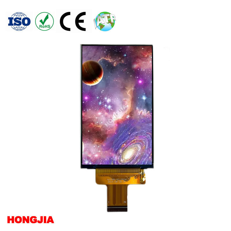
The 39-Pin SPI and 16-Bit RGB Architecture of the HJ3100-03
The 39-pin layout separates configuration duties from high-speed data transmission. This division of labor is strictly necessary for screens of this resolution.
A 480x800 3.1 inch IPS Screen 480x800 RGB pushes 384,000 pixels per frame. Running at 16-bit color depth (RGB565) and a standard 60Hz refresh rate requires moving roughly 368 megabits of data per second. A standard SPI bus chokes on that bandwidth. If you try to push full video over SPI at this resolution, you max out around 10 to 15 frames per second, resulting in a visibly sluggish interface.
Instead, the host MCU uses the 3-wire or 4-wire SPI pins purely for initialization. You send the configuration payload once at boot to set up the gamma curves, power sequence, and display orientation. After the setup commands are registered, the 16-bit RGB interface takes over the heavy lifting to stream raw pixel data continuously. The 39-pin standard provides enough dedicated data lines to keep the frame rate smooth without bottlenecking the main processor.
Integrating the ST7701 Driver IC with Embedded Host Boards
The ST7701 is a widely used driver IC for this specific size and resolution, mounted directly on the glass (COG). Getting it to talk to your host board requires strict attention to memory and timing.
An uncompressed 480x800 frame buffer at 16-bit color takes up exactly 768KB of RAM. Most entry-level microcontrollers do not have that much internal SRAM. If your selected MCU falls short, you will need to route external SDRAM on your PCB, which complicates the board layout and increases EMI.
Timing tolerances are equally unforgiving. The ST7701 expects a continuous, perfectly timed dot clock (PCLK) alongside data enable (DE), HSYNC, and VSYNC signals. Do not attempt to bit-bang a 16-bit RGB interface using general-purpose I/O pins. The host must have a dedicated RGB hardware controller (like the LTDC on STM32 chips or the LCDC on NXP parts). Missing a single clock cycle or delaying the VSYNC pulse by a few microseconds results in visible screen tearing, flickering, or a completely rolling display.
Managing Heat Dissipation in 1000-Nit Sealed Industrial Enclosures
High brightness comes at a direct thermal cost. Pushing 1000 nits through a transmissive normally black LCD means driving the backlight LEDs close to their maximum rated current. In an open-air lab setting, this is rarely an issue. Inside a sealed IP67 industrial enclosure or an outdoor handheld testing instrument, that heat gets trapped.
If you leave an air gap directly behind the screen module in a sealed device, the backlight LEDs will run hot and degrade prematurely. Within months, the screen's white balance will shift noticeably yellow, and overall brightness will drop. You have to provide a thermal escape route. Engineering teams typically specify a thermally conductive pad between the metal back of the Liquid Crystal Display module and an internal aluminum structural bracket, turning the chassis itself into a heatsink.
Customizing FPCs and Touch Panels for Handheld Medical and Industrial Devices
Off-the-shelf display modules rarely fit perfectly into specialized hardware. The standard 39-pin FPC position might clash with a battery cavity in a blood oxygen meter or force an awkward board placement in handheld beauty equipment.
Bending an FPC beyond its minimum bend radius to force a fit will cause micro-cracks in the copper traces, leading to intermittent display failures on the assembly line or in the field. SZ Hongjia Technology Shares Limited modifies the FPC length, shape, and pinout to match your specific PCB layout, eliminating the mechanical stress.
Adding capacitive touch introduces another variable. For a medical grade 3.1 inch screen, an air gap between the touch sensor and the display glass is a liability. Changing humidity environments cause condensation to form inside that gap, which ruins visibility and registers false touch inputs. Specifying optical bonding—where a clear liquid adhesive binds the touch panel directly to the TFT glass—removes the air gap, improves impact resistance, and limits internal reflections.
Securing Long-Term Supply and Low-Volume Trials for US Engineering Teams
Supply chain volatility dictates hardware design just as much as technical specs. US teams designing industrial control systems or medical equipment usually manufacture in batches of 500 or 5,000 units, not 500,000. Many display manufacturers prioritize high-volume consumer electronics and will issue an End of Life (EOL) notice on a small TFT LCD module with little warning.
Replacing a screen mid-production is an expensive mistake. It requires a new board layout, new firmware timing configurations, and in the case of medical devices, complete re-certification of the product. SZ Hongjia specifically targets the industrial and medical markets by guaranteeing long-term supply stability and accepting small trial orders for prototyping.
To successfully integrate a 480x800 module, you need an MCU with a hardware RGB controller, a 768KB frame buffer, and a physical design that accounts for backlight heat. If your hardware is ready for these requirements, you can evaluate the HJ3100-03 module to confirm pin compatibility with your host board.
Send Inquiry


X
We use cookies to offer you a better browsing experience, analyze site traffic and personalize content. By using this site, you agree to our use of cookies.
Privacy Policy