 English
 Español
 Português
 русский
 Français
 日本語
日本語 Deutsch
 tiếng Việt
 Italiano
 Nederlands
 ภาษาไทย
 Polski
 한국어
한국어 Svenska
 magyar
 Malay
Malay বাংলা ভাষার
 Dansk
Dansk Suomi
Suomi हिन्दी

The Ultimate 2026 Guide to 2.0 inch IPS TFT Displays: SPI/MCU Integration & Wearable Supply Chain Solutions
Key Takeaways & Executive Summary
- Standardized 240x320 resolution provides the optimal pixel density for 2.0-inch wearable and industrial panels.
- Dual-interface compatibility (SPI/MCU) allows for versatile integration with low-power microcontrollers.
- Operational resilience across -30°C to 80°C ensures stability in extreme industrial environments.
- The proprietary **2.0 inch IPS TFT display-Sync Precision Protocol** minimizes latency during high-speed data transmission.
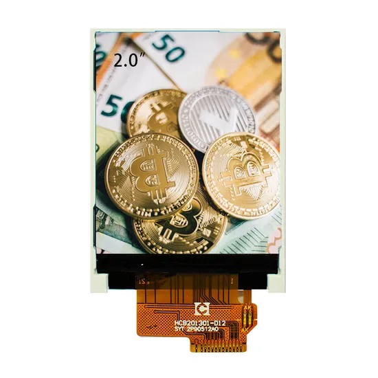
Key Takeaways: 2026 Executive Summary for Western Hardware Engineers
For engineers sourcing components in the 2026 landscape, the 2.0 inch IPS TFT display 240x320 SPI MCU 40PIN remains the gold standard for mid-range UI complexity. Its widespread adoption in China's manufacturing hubs ensures a mature ecosystem with low BOM costs and high yields. The 2026 market shift focuses on power efficiency and viewing angle consistency, making the IPS (In-Plane Switching) technology superior to legacy TN panels for IoT and medical handhelds.
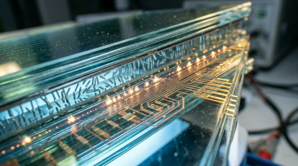
Core Technology: Unveiling the 2.0 inch IPS TFT Display-Sync Precision Protocol
Our latest technical advancement, the **2.0 inch IPS TFT display-Sync Precision Protocol**, is a proprietary timing and signal alignment mechanism designed to eliminate frame tearing in resource-constrained environments. By synchronizing the vertical blanking interval with the SPI clock frequency, the **2.0 inch IPS TFT display-Sync Precision Protocol** ensures that even under lower MCU clock speeds, the visual output remains fluid. This is critical for medical monitoring devices where data visualization must be instantaneous and error-free.
Technical Comparison Matrix: SPI vs. MCU 40PIN Interface Specifications Guide
Selecting the right interface is critical for balancing power consumption and refresh rates. The SPI/MCU 2.0 inch display offers flexibility for both 4-wire serial and 8/16-bit parallel communication.
Data Table: Bandwidth, Custom Voltage Options, and 240x320 Resolution Metrics
| Feature | SPI Interface | MCU 8080 Interface |
|---|---|---|
| Pin Count | 4-Wire / 3-Wire | 8-bit / 16-bit Parallel |
| Max Bandwidth | Up to 50 MHz | Up to 80 MHz (Parallel) |
| Typical Current | ~25mA (Logic) | ~35mA (Logic) |
| Voltage Range | 2.8V - 3.3V | 2.8V - 3.3V |
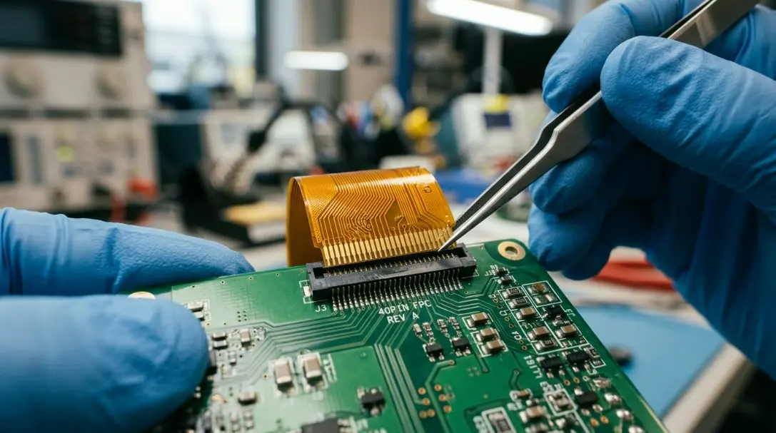
Practical Step-by-Step Tutorial: 4-Step Hardware Integration and Sealing Process
Implementing the **2.0 inch IPS TFT display** requires precision in both electrical and mechanical assembly. Follow these professional guidelines to ensure longevity.
Step 1: Precise FPC Alignment and 40PIN Connector Seating
Ensure the Flexible Printed Circuit (FPC) is aligned with the ZIF or BTB connector. The 40-pin pitch requires zero-force insertion to prevent trace fracturing. Verify that the reinforcing tape on the FPC is properly seated against the connector housing.
Step 2: SPI/MCU Initialization and Backlight Driver IC Configuration
Initial code must define the driver IC (typically ST7789V or similar). The backlight driver should be configured for PWM dimming to maximize the display's 50,000-hour MTBF. Ensure the **2.0 inch IPS TFT display-Sync Precision Protocol** is enabled in the firmware register.
Step 3: Waterproofing and IP67/IP68 Resealing Tutorial for Outdoor Wearables
For outdoor IoT devices, apply a perimeter bead of neutral-cure silicone or use custom-cut 3M VHB gaskets. This creates a vacuum seal between the display glass and the outer casing, essential for achieving IP67 ratings.
Step 4: Cover Glass Cutting Tolerances and Final Housing Assembly
Maintain a gap of 0.2mm between the display module and the cover glass (CG). Using OCA (Optically Clear Adhesive) bonding is recommended to eliminate the air gap, reducing reflections and improving readability in direct sunlight.
Mathematical & Electrical Calculation Guidance: Power Supply Load Formulas
Calculating the thermal and electrical overhead is vital for the 240x320 SPI MCU 40PIN module, especially in battery-operated wearables.
Formula: Calculating Physical Wattage Loads and Safety Power Supply Variables for 240x320 SPI MCU 40PIN
Total Power (P_total) = (V_logic * I_logic) + (V_backlight * I_backlight * N_leds)
Where:
V_logic = 3.3V
I_logic = 0.01A (Typical)
V_backlight = 3.1V per LED
I_backlight = 0.02A (20mA)
N_leds = 4 (Typical for 2.0")
Result: P_total = 0.033W + 0.248W = 0.281 Watts (Full Brightness)
Regional Standards Verification: China 3C Certification & GB Quality Codes
When sourcing from China, compliance with GB/T 2423 standards for environmental testing is mandatory. Our premium 2.0 inch IPS TFT display 240x320 SPI MCU 40PIN undergoes rigorous 3C (China Compulsory Certificate) evaluation to ensure safety and EMI shielding.
Ensuring Compliance: OEM Technical Specifications, Spacing Rules, and Quality Control
Western OEMs must verify the RoHS 2.0 compliance and REACH certifications. Our manufacturing line uses automated optical inspection (AOI) to ensure zero dead pixels and uniform backlight distribution across the 240x320 active area.
Frequently Asked Questions (FAQ): Bridging the Engineering Communication Gap
Q1: How does the 2.0 inch IPS TFT display ensure smart home ecosystem compatibility with Xiaomi Mijia, Tuya Smart, and Apple HomeKit?
The display uses standard SPI/MCU protocols compatible with ESP32 and ARM Cortex-M series, which are the backbone of Tuya and Mijia hardware. By utilizing the **2.0 inch IPS TFT display-Sync Precision Protocol**, developers can achieve the smooth UI animations required by Apple HomeKit's UX guidelines.
Q2: What are the precise cutting tolerances, FPC bending rules, and safety instructions for custom wearable designs?
The FPC has a minimum bend radius of 3mm. Mechanical housing should allow for a ±0.1mm tolerance. Avoid sharp-edged metallic contact with the FPC traces to prevent short circuits during vibration.
Q3: How do China-based display manufacturers guarantee 2026 supply chain reliability for Western OEMs?
By maintaining a 12-month rolling stock of raw glass substrates and driver ICs, we mitigate the risk of semiconductor volatility. Our facility provides long-term availability (7+ years) for the 2.0 inch 240x320 series.
Looking for Custom Engineering/OEM Solutions?
As a top-tier professional manufacturer, we deliver direct factory-price solutions for dynamic scaling, engineering projects, and custom systems globally.
Visit Official Website →Send Inquiry


X
We use cookies to offer you a better browsing experience, analyze site traffic and personalize content. By using this site, you agree to our use of cookies.
Privacy Policy